Biomedical Engineering Reference
In-Depth Information
(a)
(b)
70
70
c
d
=3
.
00
c
d
=0
.
50
c
d
=0
.
c
d
=3
.
00
c
d
=0
.
50
c
d
=0
.
60
60
50
08
50
08
40
40
30
30
20
20
10
10
0
0
-0.5
0
0.5
1
1.5
-0.5
0
0.5
1
1.5
u
r
i
[mm]
u
r
i
[mm]
(c)
(d)
70
70
c
d
=3
.
00
c
d
=0
.
50
c
d
=0
.
08
c
d
=3
.
00
c
d
=0
.
50
c
d
=0
.
08
60
60
50
50
40
40
30
30
20
20
10
10
0
0
-0.5
0
0.5
1
1.5
-0.5
0
0.5
1
1.5
u
r
i
[mm]
u
r
i
[mm]
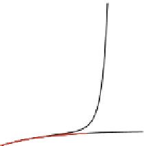
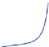
Fig. 5
Perturbed tube subjected to internal pressure and residual stresses. Variation of the reg-
ularisation parameter
c
d
in
[
kPa
−
1
mm
2
n
.The
upper
and
lower solid black lines
represent the purely elastic response of the fibre-reinforced material and the
neo-Hookean matrix. The
colored lines
represent the damage response.
a
ʱ
]
for different sets of opening angles
ʱ
M
A
=
0
.
0,
ʱ
=
0
.
0,
M
A
M
A
M
A
b
0wherethe
circular markers
are associated with a mesh of 12,000 elements. The
grey region
represents the
physiological pressure range. Units of
ʱ
=
45
.
0,
ʱ
=
90
.
0,
c
ʱ
=
60
.
0,
ʱ
=
120
.
0,
d
ʱ
=
120
.
0,
ʱ
=
160
.
n
in
ʱ
[
deg
]
(a)
(
b)
(c
)
f
d
[-]
1.00
0.92
0.83
0.75
0.67
0.58
0.50
0.42
0.33
0.25
0.17
0.08
0.00
Fig. 6
Perturbed tube subjected to internal pressure and residual stresses. Contours of the damage
function
f
d
for
ʱ
M
A
=
90
.
0
[
deg
]
at a post-peak pressure of
p
=
40
.
0[kPa].
Va r i a t i o n o f
f
d
with
a
c
d
=
0
.
08,
b
c
d
=
0
.
5,
c
c
d
=
3
.
0. Units of
c
d
in
[
kPa
−
1
mm
2
=
45
.
0
[
deg
]
,
ʱ
]