Biomedical Engineering Reference
In-Depth Information
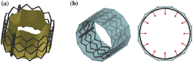
Fig. 2 a
CAD model of the Edwards Sapien
device
b
Isometric (
left
)andtop(
right
)viewofthe
crimping simulation model. In
cyan
the 12 rigid planes are shown and the radial directions of the
motion imposed to them is indicated by
red arrows
Crimping simulation.
The crimping simulationwas implemented by applying a radial
translation to 12 rigid planes placed around the TAV stent (Fig.
2
b) and compressing
it to a final external radius of 4.7mm, replicating the real procedure. A frictionless
penalty-based contact was used to manage the interaction between the stent and the
planes. At the end of the crimping phase a further step was performed, in which the
rigid planes were removed and the stent recovered part of its elastic deformation (this
phase is called
recoil
).
Deployment simulations.
The stent configuration obtained after the crimping and
recoil simulation was imported together with its residual stress and strain fields in
subsequent analyses, in which the stent was deployed within the three different AR
models H, P1and P2 at their systolic peak configurations (Fig.
3
). The deployment
simulations were performed by applying a uniformpressure (that gradually increased
from 0 to 600kPa) on the inner surface of the stent. As for the crimping simulation,
penalty-based contacts were used to manage the interaction between the stent and the
native AV, the stent and the AR wall, as well as the AV and the AR wall. Concerning
the contacts involving the stent and the biological structures, a formulation that
computes the contact forces based on the nodal mass instead of the element stiffness
was used, so to cope with the large difference in mechanical properties between
soft tissues and steel. In order to limit inertial oscillations due to the choice of a
fully-transient formulation, a damping contribution was set: the proper damping
coefficient was computed from a non-damped simulation that allowed to obtain the
critical frequency of the system.
TAV leaflet positioning simulations.
The TAV leaflet model was then positioned in
the post-implantation stent configurations through a step in which a non uniform
displacement field was applied to the nodes lying on the outer boundaries of the
leaflets (except the nodes belonging to the free edges).
TV dynamic simulations.
Once the implanted leaflet configurations in model H, P1
and P2 were obtained, dynamic simulations of TAV throughout the cardiac cycle
were performed, by applying a physiological trans-valvular pressure on the leaflet
surface. In this phase, the nodes belonging to the outer boundaries of the leaflets