Biomedical Engineering Reference
In-Depth Information
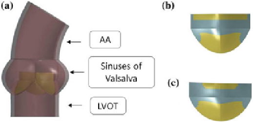
Fig. 1 a
Representation of the healthy AR model (model H) [
16
],
b
distribution of the calcific
elements on model P1 and
c
model P2 (calcifications are shown in
cyan
)
- a healthy model (model H);
- a first pathological model (model P1) obtained by introducing a typically observed
distribution of calcifications on model H;
- a second pathological model (model P2) obtained by extending the calcifications
of model P1 on the commissural zones of the AV leaflets.
Model H was taken from a previously published work by Sturla and colleagues [
16
]:
it consists of a paradigmatic physiological AR model based on MRI in vivo data
of 8 healthy subjects. The model is shown in Fig.
1
a and includes: the AR wall,
characterized by the left ventricle outflow tract (LVOT), the sinuses of Valsalva and
the first tract of the ascending aorta (AA), and the trileaflet AV. The latter was dis-
cretized with 4-node Belytschko-Tsay shell elements [
17
] with 3 integration points
along the out-of-shell direction in order to account for shell bending, while the AR
wall was discretized with reduced-integration hexahedral elements in order to limit
computational costs.
As concerns material properties, a linear elastic model was assigned to the AR
wall with a young modulus of 2 MPa, a Poisson coefficient of 0.45 and a density of
1,100kg/m
3
[
18
], while the AV leaflets were modeled with a nearly incompressible
transversely isotropic hyperelastic material. Such a model is based on the strain
energy function proposed by Weiss and colleagues [
17
] and was chosen in order to
account for the anisotropic mechanical response of the AV leaflets which is stiffer
in the direction of the collagen fibers (i.e. the circumferential direction) as shown in
the work done by Billiar and Sacks [
19
].
Model P1 and P2 differ from model H only for the modeling of the AV leaflets.
In order to model AV calcifications, in model P1 a layer of stiffer shell elements
(representing the calcifications) has been superimposed onto the healthy AV shell
elements: the distribution of the calcific elements was chosen in order to resemble
typically observed calcifications on excised stenotic AVs [
20
]. Model P2 was then
obtained by extending the distribution of the calcific elements in the commissural
zones of the leaflet. In Fig.
1
b, c the distribution of the calcific elements on one of
the AV leaflet is shown for model P1 and P2.