Civil Engineering Reference
In-Depth Information
#11 bars and smaller
(without epoxy coating)
≥
5
d
b
≥
2
.5d
b
d
b
≥
2
d
b
Figure 7-6 Typical Spacing and Cover of Reinforcement in Footings
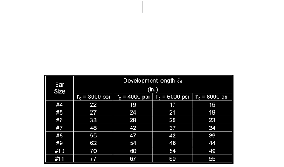
Table 7-1 Minimum Development Length
d
for Flexural Reinforcement in Footings (Grade 60)
Compression forces must be transferred by bearing on concrete and by reinforcement (if required). Bearing
strength must be adequate for both column concrete and footing concrete. For the usual case of a footing with
a total area considerably larger than the column area, bearing on column concrete will always govern until
› of the column concrete exceeds twice that of the footing concrete (ACI 10.14.1). Design bearing strength of
concrete must not exceed
= 0.65. For concrete strength
› = 4000 psi, the allowable bearing force P
nb
(in kips) on the column concrete is equal to P
nb
= 2.21 A
g
, where
A
g
is the gross area of the column in square inches. Values of P
nb
for concrete strengths 4, 5, and 6 ksi are listed
in Table 7-2 for the column sizes given in Chapter.
φ
(0.85›A
1
), where A
1
is the loaded area and
φ
When the factored column load P
u
exceeds the concrete bearing capacity
P
nb
the excess compression must be
transferred to the footing by reinforcement (extended column bars or dowels; see ACI 15.8.2). Total area of
reinforcement across the interface cannot be less than 0.5% of the column cross-sectional area (see Table 7-2).
For the case when dowel bars are used, it is recommended that at least 4 dowels (one in each corner of the
column) be provided.
φ


Search WWH ::

Custom Search