Civil Engineering Reference
In-Depth Information
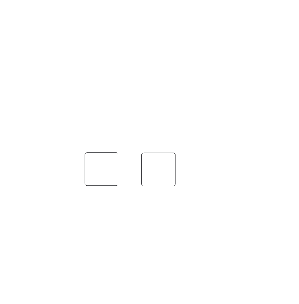
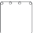
8 and 16 bar arrangements can be supported by the separate crossties shown in Fig. 5-9. Again, it is important
to alternate the position of the 90° hooked end at each successive tie location. The two-piece tie shown for the
12 bar arrangement should be lap spliced at least 1.3 times the tensile development length of the tie bar, ˜
d
, but
not less than 12 in. To eliminate the supplementary ties for the 8, 12, and 16 bar arrangements, 2, 3, and 4 bar
bundles at each corner may also be used; at least No. 4 ties are required in these cases (ACI 7.10.5.1).
Column ties must be located not more than one-half a tie spacing above top of footing or slab in any story,
and not more than one-half a tie spacing below the lowest reinforcement in the slab (or drop panel) above (see
ACI 7.10.5.4 and Table 5-2). Where beams frame into a column from four sides, ties may be terminated 3 in.
below the lowest beam reinforcement (ACI 7.10.5.5). Note that extra ties are required within 6 in. from points
of offset bends at column splices (see ACI 7.8.1 and Chapter 8).
Alt. hook
90
∞
(typ.)
Alt. hooks (typ.)
8 bars
Column
18 in.
Preassembled
Cages
Field Erection
20 in., 22 in., and 24 in. columns
1. 3
˜
d
12
Lap splice
≥
greater of
12 bars
Field Erection
All 12 bar arrangements
16 bars
Preassembled
Cages
Field Erection
All 16 bar arrangements
Figure 5-9 Column Tie Details


Search WWH ::

Custom Search