Civil Engineering Reference
In-Depth Information
To allow rapid selection of column size and longitudinal reinforcement for a factored axial load P
u
and bending
moment M
u
, Figs. 5-18 through 5-25 are included at the end of this chapter. All design charts are based on
= 4000 psi and f
y
= 60,000 psi, and are valid for square, tied, nonslender columns with symmetrical bar
arrangements as shown in Fig. 5-6. The number in parentheses next to the number of reinforcing bars is the
reinforcement ratio,
f
c
ʹ
ρ
g
= A
st
/A
g
, where A
st
is the total area of the longitudinal bars and A
g
is the gross area of
the column section. A clear cover of 1.5 in. to the ties was used (ACI 7.7.1); also used was No. 3 ties with
longitudinal bars No. 10 and smaller and No. 4 ties with No. 11 bars (ACI 7.10.5).
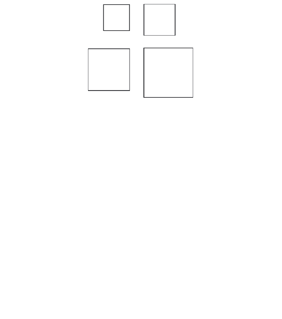
4 bars
8 bars
12 bars
16 bars
Figure 5-6 Bar Arrangements for Column Design Charts
For a column with a larger cross-section than required for loads, a reduced effective area not less than one-half
of the total area may be used to determine the minimum reinforcement and the design capacity (ACI 10.8.4),
this provision must not be used in regions of high seismic risk.
Essentially this means that a column of sufficient size can be designed to carry the design loads, and concrete
added around the designed section without having to increase the amount of longitudinal reinforcement to
satisfy the minimum requirement in ACI 10.9.1. Thus, in these situations, the minimum steel percentage, based
on actual gross cross-sectional area of column, may be taken less than 0.01, with a lower limit of 0.005 (the
exact percentage will depend on the factored loads and the dimensions of the column). It is important to note
that the additional concrete must not be considered as carrying any portion of the load, but must be considered
when computing member stiffness (ACI R10.8.4).
Additional design charts for other column sizes and material strengths can obviously be developed. For
rectangular or round columns, the graphs presented in Reference 5.2 may be used; these graphs are presented
in a nondimensionalized format and cover an extensive range of column shapes and material strengths. Also,
the CRSI Handbook
5.3
gives extensive design data for square, rectangular, and round column sections.
5.5.1.1 Example: Construction of Simplified Design Chart
To illustrate the simplified procedure for constructing column interaction diagrams, determine the points
corresponding to the various transition stages for an 18
×
18 in. column reinforced with 8-No. 9 bars, as shown
in Fig. 5-7.


Search WWH ::

Custom Search