Environmental Engineering Reference
In-Depth Information
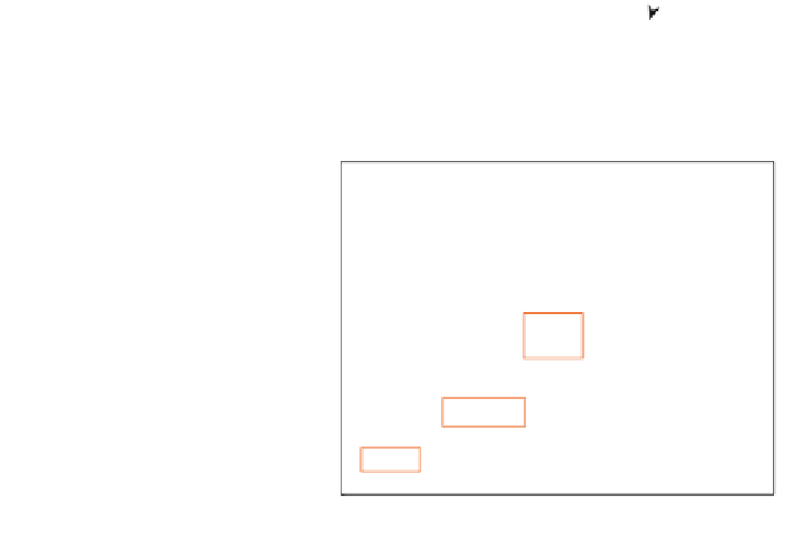
Fig. 4.9 Approximate
operating trajectory of a
500 W wind turbine
100
Starting
90
80
70
60
50
Tip
Hub
40
30
Power production
20
10
0
10
4
10
5
Reynolds number
Fig. 4.10 Reynolds number
ranges for small wind
turbines and other
aerodynamic bodies
10
6
BOEING
737
10
4
5 kW
starting
CESSNA
180
500 W
starting
10
2
SMALL
UAVs
10
0
BIRD
S
5 kW rated
power
MICRO-AVs
10
-2
500 W rated
power
INSE
CTS
10
-4
10
3
10
4
10
5
10
6
10
7
10
8
Reynolds Number
for maximum power. For the reasons given in
Chaps. 6
and
7
, starting is far more
important to small wind turbines than stopping which is not shown in Fig.
4.9
. Also
missing is any indication of the stationary blades at the extreme wind speed, one of
the load cases considered in
Chap. 9
. Nevertheless, it is clear that high angles on
small wind turbine blades are associated mainly with low Re.
Figure
4.10
, based on Fig. 1 of [
18
], shows the tip Reynolds number range for
the 500 W turbine and the Aerogenesis 5 kW turbine from
Chap. 1
in comparison
with a range of flight ''vehicles''. Micro-aerial vehicles (Micro-AVs) and unpiloted
aerial vehicles (UAVs) are commercial and military versions of model aircraft.
The use of blade mass for the vertical scale is not strictly useful for wind turbines
but it does separate the data. The range of Re for wind turbine blades comes about


Search WWH ::

Custom Search