Environmental Engineering Reference
In-Depth Information
A ''diffuser augmented wind turbine'' (DAWT) has a diffuser installed downstream
of the blades (and sometimes a concentrator upstream) to force the wake to expand
more rapidly than it would otherwise. This increases the air flow through the blades.
It is easy to design a DAWT whose performance exceeds the Betz-Joukowsky limit.
It is, however, generally thought that the structural and other problems of DAWTs,
such as the difficulty in responding to changes in the wind direction, make them
unsuitable in practice.
In a form similar to (
2.16
), the thrust coefficient, C
T
, can be derived from
Eqs.
2.5a
,
b
and
2.11
, giving
T
C
T
¼
2
qU
0
pR
2
¼
4a 1
a
ð
Þ
ð
2
:
19
Þ
1
so that at optimum performance, C
T
= 8/9, and has an upper limit of unity when
a = 1/2 according to (
2.19
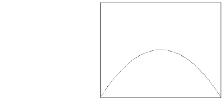
). In practice, it seems that C
T
is about 0.9 at maximum
performance, but there are a number of measurements of C
T
exceeding unity as
a increases above 1/3. Some of these are shown in Fig.
2.2
. High thrust coincides
with C
P
decreasing towards the runaway value of zero, and increasing wake
expansion. A further failing of the simple analysis is that Eq.
2.15
gives U
?
= 0
when a = 1/2, and negative U
?
for larger values, but, unfortunately there are no
detailed measurements available for the high thrust region to suggest an appro-
priate modification to (
2.15
). The experimental data shown in the figure are the
smoothed data from Table 7 of [
2
]. Additional data are given by Buhl [
3
] and
Fig. 13.5 of [
4
]. The measurements must be treated with caution, because a was
not measured directly, and the rotor swept area was a considerable fraction of the
wind tunnel cross-sectional area, so that its blockage was high. The difference
between the diamonds and the crosses in Fig.
2.2
is that the upstream ''free-
stream'' velocity, equivalent to U
0
, was used for the latter, but the measured ''free-
stream'' velocity at the rotor was used for the former. Of course, the two would be
equal
in
the
absence
of
blockage.
The
consensus
among
the
wind
turbine
Fig. 2.2 Thrust coefficients
at high axial induction
2
1.5
1
Equation (2.19)
Equation (2.20)
Equation (2.21)
Lock et al. (1925)
Lock et al. (1925)
0.5
0
0
0.2
0.4
0.6
0.8
1
Axial induction factor, a


Search WWH ::

Custom Search