Environmental Engineering Reference
In-Depth Information
Fig. 12.6 Simplified
analysis of cable tensions
during raising and lowering a
small wind turbine
turbine &
tower
gin pole
mg
β
cable
L
θ
cable
T
L
GROUND
Tower hinge point
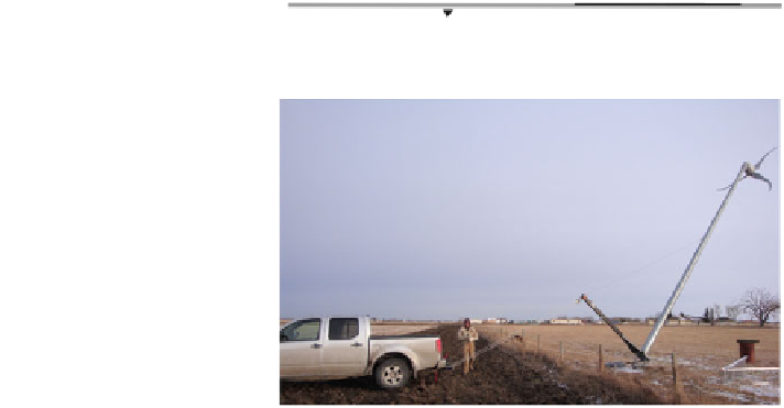
Fig. 12.7 A Skystream
2.4 kW wind turbine on a
monopole tower being raised
using a gin pole and winch
attached to a four-wheel drive
vehicle. Photograph by Rob
Falconer, Enmax Corporation
The load of interest is the cable tension T. Once it is known, the stresses in the
gin pole, tower, and foundation can be calculated. Taking moments about the
tower hinge point and noting that the gin pole, cable, and distance from the pulley
to the tower hinge form an isosceles triangle, it is easy to show that the factor f
T
relating T to the tower weight, is given by
f
T
¼
TL
cos h
sin h
þ
b
mgl
¼
ð
12
:
4
Þ
ð
ð
Þ=
2
Þ
and the maximum value of f
T
is
f
T
;
max
¼
1
=
sin b
=
2
ð
Þ
ð
12
:
5
Þ
and so lies between H2 = 1.41 and about 1.8. The loads required for foundation
design are the horizontal force, base overturning moment, and vertical force. On
calm days the wind loads are obviously zero. The vertical, compressive load on the
foundation during raising and lowering, F
yb
, is given by
F
yb
¼
mg 1
þ
l
ð
12
:
6
Þ
L
cos h
so that the maximum value, F
yb,max
, is (Fig.
12.6
)
F
yb
;
max
¼
mg 1
þ
l
=
L
ð
Þ
ð
12
:
7
Þ


Search WWH ::

Custom Search