Environmental Engineering Reference
In-Depth Information
Gearbox resistance arises partly from oil seal friction on the high speed side, and
partly in the bearings for the lay or pinion shaft of an inline gearbox. This is
particularly noticeable in gearboxes with pre-loaded taper-roller bearings on that
shaft. The small size of the resistive torque makes it unimportant for nearly all
gearbox applications and it has not been studied in any detail. In fact, most
gearbox manufacturers will scratch their heads if asked about its magnitude.
Gear losses are often divided into speed-dependent and load-dependent com-
ponents, e.g. Heingartner and Mba [
9
], of which only the former are of interest for
starting. Examples include meshing and windage losses which tend to scale on X
2
,
and generally do not significantly increase the resistive torque.
11.4 Rectifiers, Inverters, and Basic Control
This is the area of greatest and continuing advance in turbines of all sizes. Iov and
Blaabjerg [
10
] briefly describe the development of power electronics for large
wind turbines and the history of the various technologies that have increased
functionality and programmability while reducing size and cost. They also review
the main converter (rectifier and inverter) topologies in use today and provide
valuable information on the requirements for grid connection in terms of generator
synchronisation, reactive power control, and protection against grid faults. Several
excellent topics have been written on the electronics and control of large turbines
for grid connection, e.g. Munteanu et al. [
11
] which has a number of case studies
involving simulation of a 6 kW turbine as documented in their Appendix A. Many
of the basic features of power electronics are independent of turbine size.
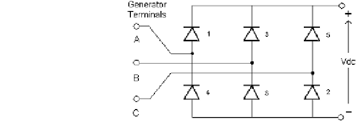
One of the simplest power converters is the diode rectifier as diodes turn on and
off naturally without the need for any control electronics. A 3-phase diode rectifier
is shown in Fig.
11.6
, where A, B, and C represent the three phases of the gen-
erated AC. The diodes have been numbered 1-6 in the standard manner corre-
sponding to the order in which the diodes turn on. Normally, two diodes are on at
the same time; one diode in the top half of the rectifier providing output current,
and one diode in the bottom half of the rectifier providing a return path for the DC
Fig. 11.6 Schematic of a
3-phase diode rectifier
Search WWH ::

Custom Search