Environmental Engineering Reference
In-Depth Information
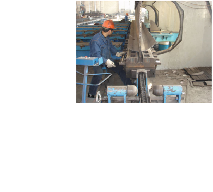
Fig. 10.1 Bending half an
octagonal tower section at a
factory in China
e.g. Clifton-Smith and Wood [
11
]. Note that the t is constant within each section—
see Fig.
10.1
—but can vary between sections. Adding the axial stress due to m
tt
and the tower self-weight, m
t
(y) above y, gives
r
max
¼
r
b
;
max
þ
m
tt
þ
m
t
ðÞ
½
g
ð
10
:
9
Þ
A
ðÞ
where g is the acceleration due to gravity, and the cross-sectional area, A(y), is
h
i
3
:
3137td
ðÞ
t
A
ðÞ¼
2
Þ
2
p
d
2
1
þ
2
ðÞ
d
ðÞ
2t
ð
½
ð
10
:
10
Þ
Since the numerator of (
10.7
) increases as y
4
and the denominator increases as
y
3
, the maximum stress in each section will occur at the start of its lower slip-fit
zone. Furthermore, the increase in the stresses with y usually requires t to be
increased in the lower sections. Multi-sectioned towers, therefore, can use a range
of section thicknesses to reduce tower mass and cost, but this must be balanced
against the requirements of slip fitting, and the availability of steel sheet of
appropriate thickness.
Two other important considerations follow from this analysis. The first is that
the upwind face of the tower is in tension and the downwind face is in com-
pression, so it is possible for the tower to buckle and this must be designed against.
The axial loads in (
10.9
) will always make the maximum compressive stress larger
in magnitude than the maximum tensile stress. Second, the wind direction can vary
randomly so it must be assumed that the maximum stress acts on the seam weld
between each half-section. This argument applies even for sections of diameter
smaller than shown in Fig.
10.1
which can sometimes be fabricated with only one
weld. The location of the maximum stress in a weld often reduces the safety factor
that can be used.
Search WWH ::

Custom Search