Environmental Engineering Reference
In-Depth Information
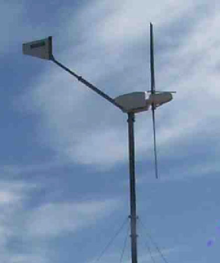
5. The tail fin for the Aerogenesis 5 kW turbine shown in Fig.
1.2
is sketched
above. The fin is made from 3 mm steel plate of density 7800 kg/m
3
. Estimate
the inertia, natural frequency and damping ratio of the fin on its own. Recal-
culate these values using the total inertia of tail fin, turbine, and blades about
the yaw axis of 58.05 kg m
2
.
6. If the tail boom has a constant but small cross-sectional area, A
b
, then its
moment of inertia about the yaw axis, I
boom
,isq
b
A
boom
r
3
3
;
where q
boom
is the
density of the tail boom material. Hence show that if c/r
1, where c is the tail
fin chord, then the total moment of inertia of the boom and fin is approximately
I
q
b
A
b
r
3
3
þ
m
tail
r
2
7. Determine the limits on the designer's ability to adjust the damping ratio and
natural frequency by altering the tail boom length.
8. Assume that the yaw moment of inertia is dominated by that of the rotor and
tail fin and that all component lengths scale on tip radius R. How will the
damping ratio in yaw change with increasing R? You may wish to review
Sect. 1.9
at this point.
9. Do a web search of manufacturers of wind turbines in the range 40-100 kW.
Do any of these have tail fins? Comment on the answer to this question.
Search WWH ::

Custom Search