Environmental Engineering Reference
In-Depth Information
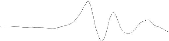
Fig. 8.12 A large wind direction change coupled with a large gust for the turbine in Fig.
6.1
from Wright [
21
]
8.7.1 Furling
Furling to prevent rotors from over-speeding has been used since before the
twentieth century in the old ''American'' high solidity water pumpers which had
no electrical system, e.g. Kentfield [
22
]. Furling is cheap and easy to implement.
A common furling system is illustrated in Figs.
8.13
and
8.14
for the 500 W
turbine from Fig.
6.1
. The yaw axis is offset from the rotor axis by a small
distance, and the tail fin boom is fixed to the rear of the nacelle by a hinge that is
tilted at angle d (10 in this case) from vertical. This hinge is the furl axis shown as
the solid white line in Fig.
8.14
. In low winds, the thrust on the rotor acting on the
yaw axis offset causes the turbine to operate at a constant, hopefully small yaw
angle, balanced by the restoring tail fin moment. The tail is held in place about the
furl axis by its own mass. As the wind speed increases, both the rotor thrust
moment and the tail fin moment increase. Eventually the gravitational moment of
the tail fin about the furl axis is exceeded by the aerodynamic moment on the tail
fin, and the tail begins to collapse or furl behind the nacelle. This turns the rotor
out of the wind direction, thus reducing its speed and power output.


Search WWH ::

Custom Search