Environmental Engineering Reference
In-Depth Information
Table 8.1
Symbols used in
Symbol
Source
Comments
Fig.
8.3
Equation
8.2
AR = 1.73
9
Kegelman and Roos [
26
]
R= 1.46
*
Torres and Mueller [
18
]
Flat plate AR = 1.75
h
Traub et al. [
27
]
AR = 1.46
+
Wentz and Kohlman [
28
]
R= 1.86
D
Matsumiya et al. [
29
]
AR = 2.0
O
Koenig [
30
]
AR = 1.0
—
Present estimate
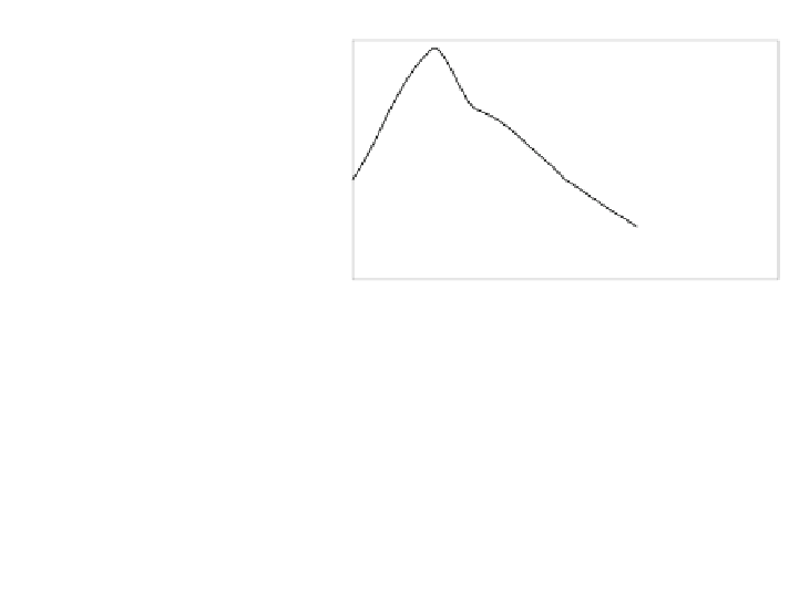
Fig. 8.3 a Composite
approximation of lift
coefficient for delta fin of
AR = 1.73 from Wright [
21
].
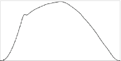
b Composite approximation
of drag coefficient for delta
fin of AR = 1.73 from
Wright [
21
]
(a)
1.40
1.20
1.00
0.80
0.60
0.40
0.20
0.00
0
20
40
60
80
100
120
140
160
180
-0.20
-0.40
-0.60
-0.80
-1.00
angle of attack (deg)
(b)
1.20
1.00
0.80
0.60
0.40
0.20
0.00
0
20
40
60
80
100
120
140
160
180
angle of attack (deg)
It is generally held that the aerodynamics of delta wings are much less
Re-dependent than that of aerofoils, mainly because the flow is dominated (for all
Re) by the separation which is fixed at the leading edge. Otherwise, there are
interesting similarities to aerofoil lift and drag in that lift is nearly linear in a at
small angles, and the drag coefficient is maximised at a = 90.
Polhamus [
6
,
7
] derived the following equations for the lift and drag of delta
wings:
C
L
¼
K
p
sin a cos
2
a
þ
K
v
cos a sin
2
a
and
C
D
¼
C
L
tan a
ð
8
:
2
Þ
where K
p
and K
v
depend on the aspect ratio, e.g. Bertin and Cummings [
8
]. Note
that the relation between lift and drag is the same as for the high-a flat plate


Search WWH ::

Custom Search