Environmental Engineering Reference
In-Depth Information
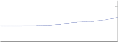
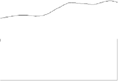
Fig. 8.1 Gyroscopic loads
on blade root of the turbine in
Fig.
6.1
. The top part shows
wind and rotor speed and yaw
rate. Bottom part shows
measured blade root bending
moment in Nm (solid line
with symbols), the short-term
averaged bending moment in
Nm (solid line) as explained
in the text, and the envelopes
of the deviation from the
average as given by Eq.
8.1
.
The origin for time is arbi-
trary. Data from Sturt Wilson
100
Ω
(rad/s)
10U (m/s)
50
ω
(rad/s)
0
40
average + 2J
Ωω
20
0
average - 2J
Ωω
-20
0
0.5
1
1.5
2
2.5
3
Time (s)
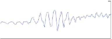
Equation
8.1
gives the maximum magnitude of the cyclic gyroscopic component.
Figure
8.1
demonstrates these loads for the turbine depicted in Fig.
6.1
. Special
blades were made, one with strain gauges embedded on the pressure (upwind)
surface and the electrical connections placed inside the blade to minimise the
aerodynamic interference. To maximise the strains, the blades were made delib-
erately weak. The blade root bending moment plotted in the bottom part of Fig.
8.1
was calculated from the measured strains. Also measured were the wind speed,
yaw rate, and rotor rpm. The bending moment is caused by the aerodynamic
pressure on the blade surface giving the ''short-term averaged'' moment and the
cyclic gyroscopic load whose period corresponds to X. For this moment, k
N
= 2in
Eq.
8.1
, and Fig.
8.1
shows that this envelope is a good fit to the data. It is clear
from Fig.
8.1
that the (unsteady) cyclic load is ''activated'' by the high yaw rate
centred at time = 1.5 s.
To avoid large gyroscopic loads the tail fin must be designed to prevent the
turbine following ''high frequency'' wind direction changes, but it must follow the
''low frequency'' wind direction changes to maximise output power. Finally, one
of the major ways of protecting small turbines against over-speeding, either in high
winds or when the electrical load has been lost, is furling. This involves collapsing
the tail fin at hopefully, a predictable and repeatable wind speed and loading. For
micro turbines, an alternative is to pitch the turbine out of the wind, a technique
that also must take account of the gyroscopic moments. Larger turbines may use a
brake which is discussed along with electronic speed control in
Chap. 11
.
8.2 Fundamentals of Tail Fin Aerodynamics
Large wind turbines have a wind vane on or near the nacelle, and use a motor to
drive the turbine about the yaw axis to keep it pointed into the measured wind
direction—this type of yaw system is called ''active yaw''. Additionally, this yaw


Search WWH ::

Custom Search