Environmental Engineering Reference
In-Depth Information
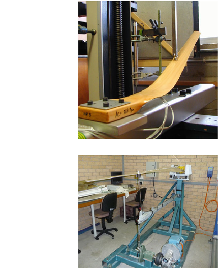
Fig. 7.13 Static test of a
0.87 m long timber blade at
the University of Newcastle
(photograph by Paul
Peterson)
Fig. 7.14 The 2.5 m long
blade from Fig.
7.6
in the
fatigue test rig at the
University of Newcastle
ready for testing. The electric motor at the bottom right is controlled by the
variable frequency drive at the top right. The blade is shaken by the hinged
horizontal arm attached via a vertical rod at the 2/3rd radius point, chosen as being
close to the centre of pressure for thrust loads that are proportional to radius, such
as those shown in Fig.
5.6
. Amplitude variation requires a manual adjustment to
the vertical, eccentrically-mounted arm in the bottom centre of the photograph.
Note that the blade is mounted at an angle to the horizontal: this angle is also its
pitch angle on the actual turbine. A number of strain gauges are mounted along
the blade. Their output is collected by the data logger in the cabinet mounted on
Search WWH ::

Custom Search