Environmental Engineering Reference
In-Depth Information
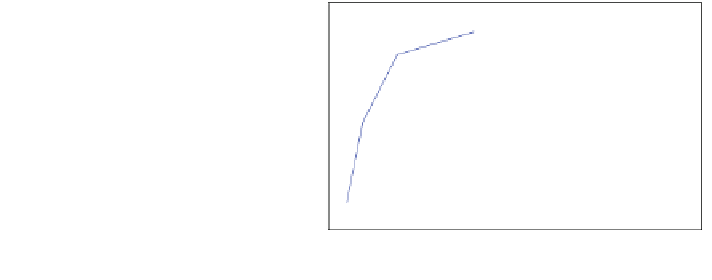
Fig. 7.5 The optimal fitness
front for the blade design
example
0.50
Q
r
= 0.5 Nm
a = 1.0
a = 0.9
0.49
a = 0.9
a = 0.8
target C
P
= 0.481
0.48
Q
r
= 0
0.47
a = 0.8
a = 0.7
1.5
2
2.5
3
3.5
4
4.5
Starting time, T
s
(s)
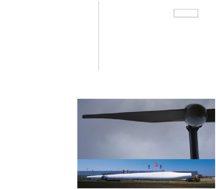
Fig. 7.6 The Aerogenesis
2.5 m long blade compared to
the LM Glassfiber 61.5 m
blade from
www.lmwindpower.com
(accessed 4 Aug 2010)
power requires Nc to be roughly constant—but the biggest differences in shape
occur at the tip and at the hub. Near the hub, the wider chord improves the starting
behaviour with two blades and relatively high resistive torque. Sharp tips on the
large blades reduce the noise associated with the formation of the tip vortex:
Oerlemans et al. [
2
] found that modern tips like that shown in Fig.
7.6
effectively
eliminate tip noise.
Calculations by Clifton-Smith [
3
] suggest that tip noise is not a major noise
source for small blades provided the tip is rounded. However, as power level
increases, more attention should be paid to the tip design to reduce noise. Clifton-
Smith [
3
] included noise as one objective function for the design of 3 m diameter
blades. He found that the BET optimum blade was the noiseist, but that a sig-
nificant reduction in both starting time and sound power level were achievable
with only a small drop in C
P
.
Determining the basic blade shape from aerodynamic optimisation is the
essential first step in the design process but there is still considerable work to do to
produce an actual blade that performs as designed and is structurally sound.
At this point the blade connection should be considered, bearing in mind that
the thick sections seen near the hub on the large blade in Fig.
7.6
are to be avoided
for small blades.
Chapter 4
explains the reasons for this statement which are


Search WWH ::

Custom Search