Hardware Reference
In-Depth Information
FIGURE 4.18
Details of “naked” Bear Chamber control board and wiring.
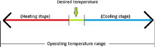
After you set the desired temperature (
T
in °C) and the controller to ON, the controller will
acquire the actual temperature from the sensors and compare with the desired temperature.
Depending on the result, the system will enter a heating or cooling stage, where the power
resistors or the cooler will be activated. This is shown schematically in
Figure 4.19
.
FIGURE 4.19
Operating temperature range of Bear Chamber.
When the temperature reaches a satisfactory range, it will be maintained by activating the
heaters or the cooler only when necessary. This is just good energy management, but is critical
depending on your application (e.g. if you are using the Bear Chamber in the field powered
with a solar photovoltaic system). A satisfactory temperature range for our application is from
0.5 °C below the desired temperature to the set point (desired value); in another words, if the
desired temperature is
T
, the range is [
T
− 0.5 °C;
T
].
The humidity controller is similar to the temperature controller. After you set the desired
relative humidity (H in %) and set the controller to ON, the controller will acquire the actual
relative humidity inside the chamber from the sensor and compare with the relative humidity
wanted. Again, depending on the result, the system will enter a humidifying or drying stage,
where the humidifier or the fan will be activated. This is shown schematically in
Figure 4.20
.

Search WWH ::

Custom Search