Hardware Reference
In-Depth Information
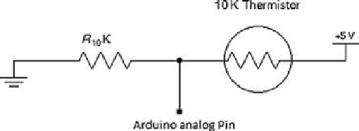
FIGURE 4.7
Circuit diagram for thermistors.
The humidity sensor (HH10D) needs to be wired as shown in
Figure 4.8
. It is connected to
the Aurdino and the MOSFET (ZVN4424A).
FIGURE 4.8
Wiring diagram for the humidity sensor.
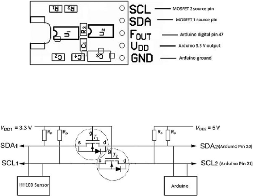
midity sensor must be wired through a Logic Level Shifter circuit as shown in
Figure 4.9
[
3
]
.
FIGURE 4.9
Wiring diagram for level shift circuit.
Search WWH ::

Custom Search