Hardware Reference
In-Depth Information
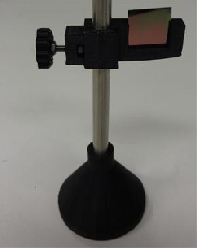
FIGURE 6.16
Sample holder.
Both holders can be adjusted for other sizes of filters or lens easily using OpenSCAD. The
kinematic mirror or lens mount shown in
Figure 6.13
was developed by Thingiverse user or-
daos and is partially parametric design used for steering optics. It contains a living hinge in
one corner and two magnets in the adjacent corners, which are atracted to a pair of set screws
used to adjust the mirror angle. The static fiber-optic holder was designed to hold a 7.7-mm-
diameter fiber-optic cable. The screen holder is designed to support a screen or card and can
be mounted on optical rail with an M3 screw-nut pair. This semiconductor sample holder
shown in
Figure 6.16
is designed to hold a semiconductor wafer piece on a smooth 8-mm-dia-
meter rod (again leftover parts from RepRap builds covered in the last chapter). It allows you
to change samples easily using tweezers with only one hand. More complex, multicomponent
optics equipment setups can also be fabricated using this method such as an open-source lab
seen in
Figure 6.17
. Again, you can easily adjust or customize the platforms of the lab jack to
hold any other type of mount for your own experiments. This makes the open-source lab jack
far superior in terms of customized utility to the standard ones that in general are just simple
lat platforms.
Search WWH ::

Custom Search