Hardware Reference
In-Depth Information
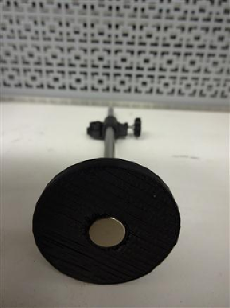
FIGURE 6.10
Magnetic optics base with rod holder.
Numerous components can then be coupled to the 8-mm-diameter smooth rods and adjus-
ted in the
z
-vertical axis to build up an optical assembly including a static filter or lens squar
e
21
(
Figure 6.11
) or circular holder
22
(
Figure 6.12
), kinematic mirror or lens holder
23
(
Figure 6.13
),
static fiber-optic holder
24
(
Figure 6.14
)
, screen holder
25
(
Figure 6.15
) and sample holder
26
(
Fig-
a filter bracket, while for the circular holder, a set screw is applied as shown in
Figure 6.12
.
Search WWH ::

Custom Search