Hardware Reference
In-Depth Information
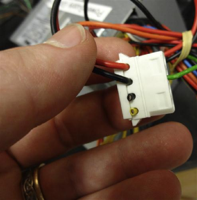
FIGURE 5.56
Shorted the green wire with black ground in order to provide the 12 V from the
power wires.
5.2.12 Adjust the trim pots for motors
Next, find the trim pot on your board, it is located to the right of your stepper driver and
below the large capacitors (below stepper driver and to the left of the large capacitor if you are
looking at it while mounted on the frame). It will have a screwdriver like top surface. Notice
that on the left side of the trim pot, there is a single large tab at the base and on the right side,
the USB, plug it in now. You do not need to power the entire board to adjust the trim pots.
Ensure that the power selection jumpers are set to USB as well. The USB power is enough to
allow for trim pot voltage readings. Next, use a multimeter and set it to DC voltage within the
range for 0-1 V. Measure the voltage from the trim pot, red probe goes to the left side, and
single tab of the trim pot. While the black probe goes to GRND (feel free to use the GRND
from JP16). Be careful not to slip—you may short something! The voltage by factory default
should be around 0.7 V or so, which is high for most motors. Melzi has a sense resistor value
Search WWH ::

Custom Search