Hardware Reference
In-Depth Information
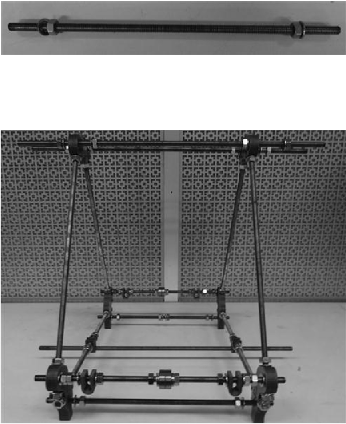
Then follow
Figure 5.9
for the idler end botom rod (idler side): washer, nut, nut, and wash-
er. Mount rods to the frame with a washer and a nut on each side are shown in
Figure 5.10
. It
does not mater which side at this point of the build. Again, remember to leave the assembly
loose at this point—tightening will take place later.
FIGURE 5.9
Assembly of the idler end bottom rod (idler side) for the
y
-axis.
FIGURE 5.10
Mounted
y
-axis rods to the frame.
5.2.5 The
z
-axis (up and down)
First, obtain all the
z
-axis components shown in
Figure 5.11
.
Search WWH ::

Custom Search