Graphics Programs Reference
In-Depth Information
3.
Select the slope arrow, and modify the parameters as shown in
Figure 3.7 so they match the location of the upper and lower floors.
Be sure to specify the Height Offset for the tail and head.
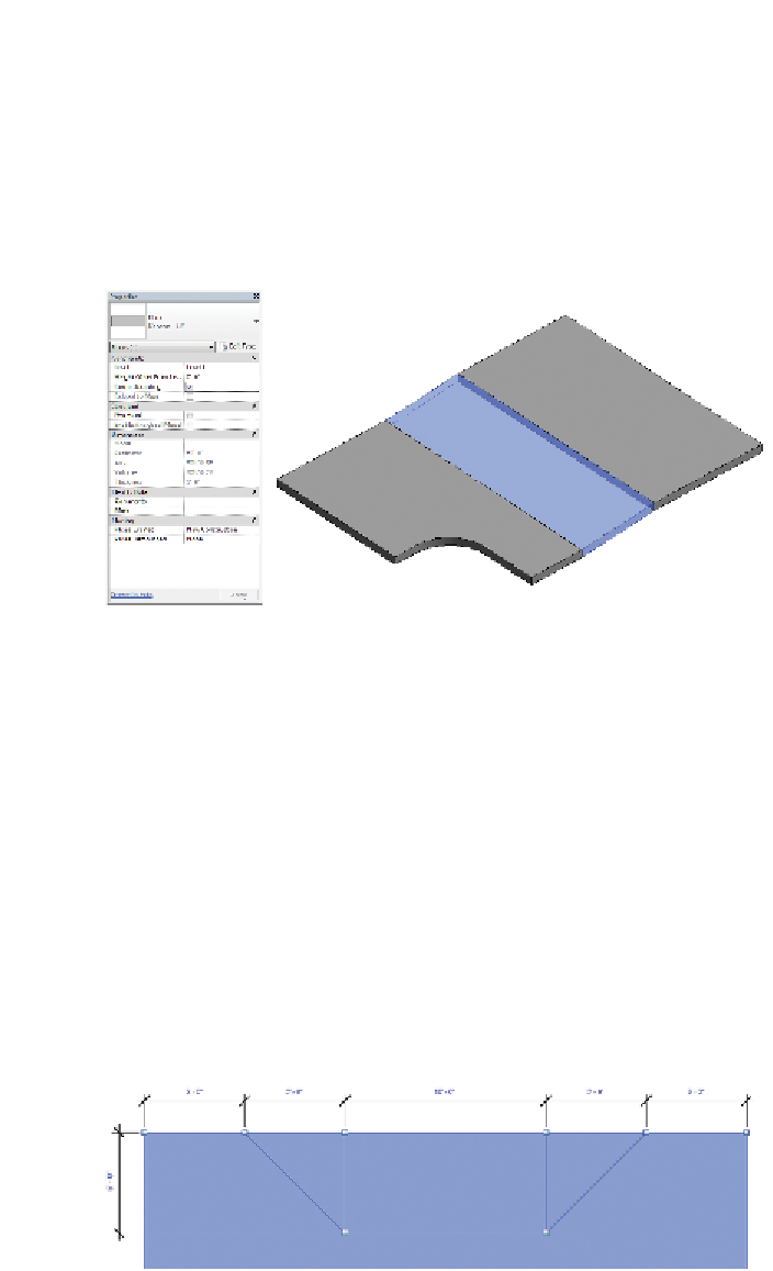
4.
Finish the sketch, and return to your default 3D view (Figure 3.8),
which shows the finished condition. Now the sloped floor connects
the lower and upper floors.
Figure 3.8
Completed sloped floor
You could create slightly sloped floors and depressions with slope
arrows and separate floors, but this approach would probably be too
complex because you'd have to create a lot of separate pieces of geom-
etry. For these kinds of conditions, you have the Shape Editing tools.
5.
Select the upper floor. Now you can see the Shape Editing tools in
the Shape Editing panel on the Modify Floors tab.
6.
Let's suppose that this entire floor is at the correct level, except for
one small portion that needs to be slightly depressed in order to
accommodate a loading area. Define the upper and lower bound-
aries of this depressed area by selecting the Add Split Line option
on the Shape Editing panel. Add the lines as shown in Figure 3.9.
Dimensions are shown for reference.
Figure 3.9
Adding split lines


Search WWH ::

Custom Search