Graphics Programs Reference
In-Depth Information
Sketch Ceiling tool
The Sketch Ceiling tool is useful for customized condi-
tions, such as a ceiling soffit or bulkhead where it is necessary to draw the
boundary, or simply for boundaries where the ceiling objects do not span the
entire space.
The objective of the following exercise is to first create ceilings automatically.
Then you will create a more custom, sketch-based ceiling.
exercise 3.10: add automatic and Sketch
Ceilings
download the files for Chapter 3, and open the file
c03-ex-3.10start.rvt
.
1.
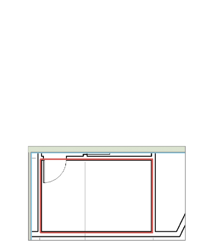
Using the Automatic Ceiling option, add a ceiling toward the bot-
tom of the image (Figure 3.28). As you hover over the space, Revit
Architecture indicates the boundary.
Figure 3.28
Revit Architecture outlines the boundary.
2.
As you can see from the Properties dialog, Revit Architecture offers
four default ceiling types: one basic type and three compound types.
Select the 2
′
×
2
′
(600 mm × 600 mm) system.
3.
When you click to place the first ceiling in the floor plan view, you get
a warning. This can happen frequently: You've placed the ceiling, but
you can't see it. As a rule, you shouldn't ignore warnings because you
could place multiple ceilings in the same place. Open the view Ceiling
Plans - Level 1, which has ceiling objects visible.


Search WWH ::

Custom Search