Biomedical Engineering Reference
In-Depth Information
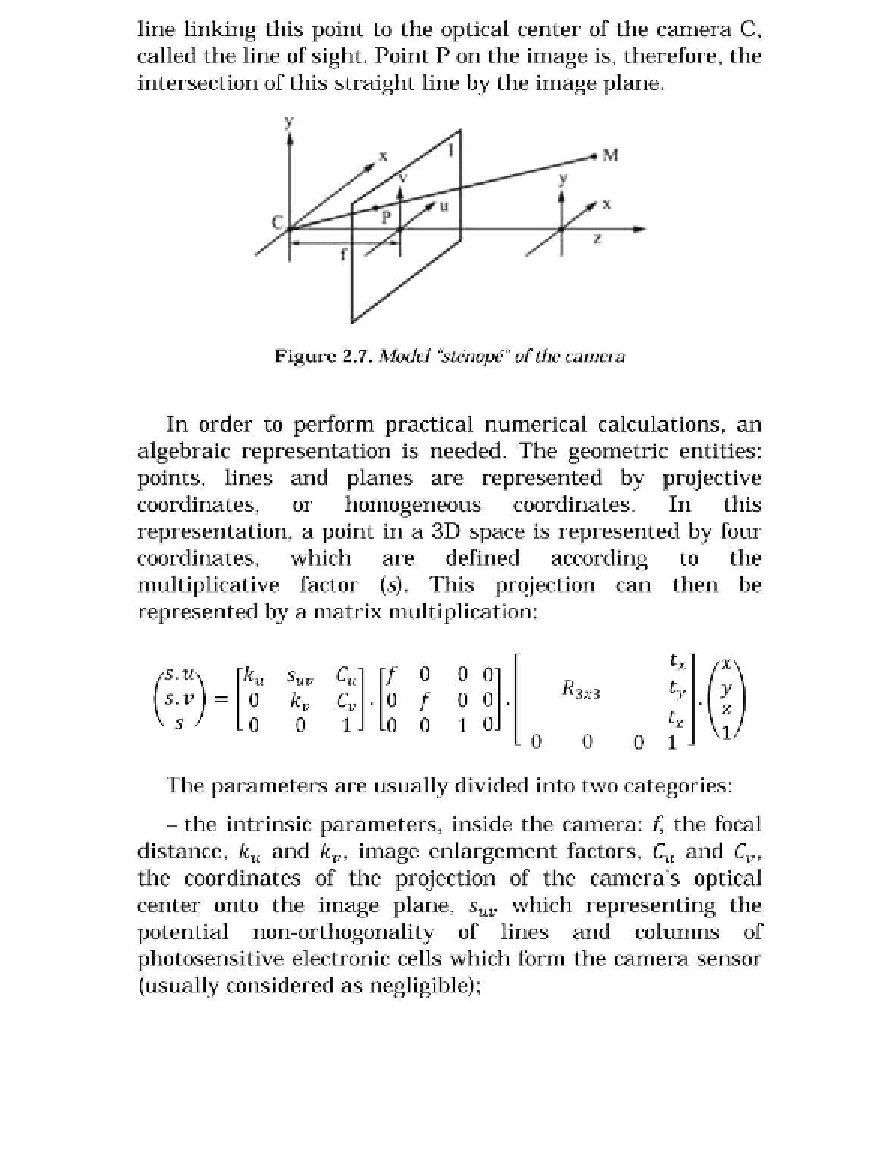
line linking this point to the optical center of the camera C,
called the line of sight. Point P on the image is, therefore, the
intersection of this straight line by the image plane.
y
Figure 2.7.
Model "stenope" ofthe camera
In order to perform practical numerical calculations, an
algebraic representation is needed. The geometric entities:
points, lines and planes are represented by projective
coordinates, or homogeneous coordinates. In this
representation, a point in a 3D space is represented by four
coordinates,
which
are
defined
according
to
the
multiplicative factor
This
projection
can then be
(5).
represented by a matrix multiplication:
Cuj
[f
s.
U)
[ku
suv
0
s.
v
=
0
C
v
.
0
f
100
kv
(
s
0
0
o
o
The parameters are usually divided into two categories:
- the intrinsic parameters, inside the camera:
f,
the focal
distance,
ku
and
kv'
image enlargement factors,
C
u
and
C
v
,
the coordinates of the projection of the camera's optical
center onto the image plane,
Suv
which representing the
potential non-orthogonality of lines and columns of
photosensitive electronic cells which form the camera sensor
(usually considered as negligible);