Environmental Engineering Reference
In-Depth Information
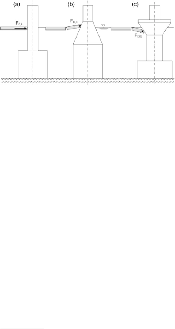
Fig. 2.51 Ice load scenarios for offshore structures: a) vertical surface, b) ice cone, c) inverted ice
cone
According to [26]
3)
, the ice loads on large structures can be calculated as follows:
a) For compression failure (in front of vertical surfaces):
F
0
;
k
¼
10
k
s
0
;
k
h
½
kN
=
m
b) For bending failure (in front of inclined surfaces)
F
B
;
k
¼
1
:
0
k
s
B
;
k
h
tan
b ½
kN
=
m
where
k contact coefficient, generally k
¼
0.33
s
0,k
characteristic compressive strength [MPa]
s
B,k
characteristic flexural tensile strength [MPa]
h
thickness of ice [cm]
b
angle of inclination of loaded area from the horizontal (compression failure
governs when
b>
80
)
Figure 2.51 shows the various scenarios connected with the incidence of ice on an
offshore structure.
The ice loads due to flexural tensile failure are lower than those as a result of com-
pressive failure and so the designer is recommended to include inclined surfaces (ice
cones) in the splash zones of foundations, especially compact foundations.
Ice loads on inclined surfaces of structural members (e.g. foundations with a conical
form in the splash zone) may be calculated with the help of Ralston's formula (see [24]
Appendix L):
a) The following applies for horizontal components:
t
2
þ
A
2
g
w
t
b
2
þ
A
3
g
w
t
ð
b
2
b
T
Þ
A
4
R
H
¼½
A
1
r
f
3)
Owing to a printing error, the reader is advised to consult the 1996 edition of the EAU!