Environmental Engineering Reference
In-Depth Information
The following generally applies for group A (accidental, earthquake):
E
dA
¼
X
E
Gk
;
j
þ g
PA
E
Pk
þ
E
Ad
þ
X
j
1
g
GA
;
j
i
1
g
QA
;
i
E
Qk
;
i
The following applies in particular for an explicit consideration of the design load cases
for design load case 2.2 (system failure, see Table 4.4):
A
d
DLC 2
:
2
E
dA
¼
X
j
1
g
GA
;
j
E
Gk
;
j
þ
1
:
00
E
Pk
þ
1
:
10
E
QV
hub
Þ
þ
E
QH
s
ðÞ
Þ
þ
E
QN
;
k
ð
ð
ð
Þ
4.7.3 Analysis of stresses in tower shaft
The design values for the internal forces (M
Ed
,N
Ed
) are taken from the deformation
analysis (see Section 4.7.1). The stresses are calculated on the basis of a linear
strain curve according to Section 3.5 with the help of the stress-strain curves
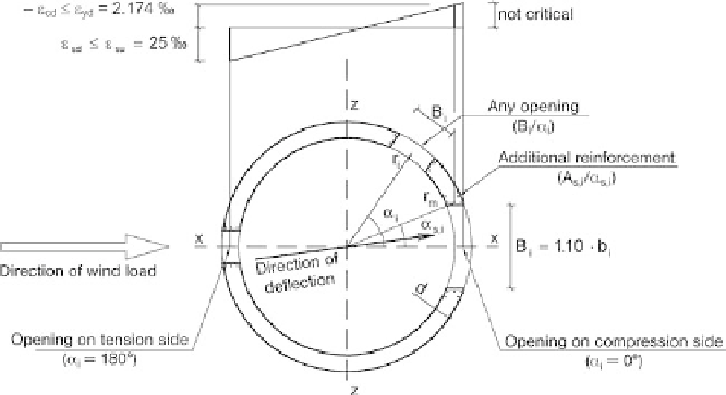
(Figures 3.10 and 3.11). The analysis must take into account openings in the
shaft wall (width B
i
, Figure 4.17); Section 4.7.4 deals with the design of such
openings.
In contrast to Section 3.3.3, the stresses may be related to the shell middle surface, so
the bending stiffness of the shell is excluded. The error associated with this is negligible
for thin shells.
The final strains are determined iteratively with the help of the equilibrium conditions
between the internal forces and the external internal forces (N
Ed
,M
z,Ed
):
Fig. 4.17 Taking into account openings in the cross-section and additional reinforcing steel