Environmental Engineering Reference
In-Depth Information
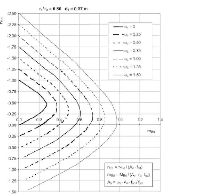
Fig. 3.12 Design chart for an annular cross-section with r
i
/r
a
¼0.80, d
1
¼0.07m; valid for concrete
grades C 12/15 to C 50/60
As an example, a design chart for annular cross-sections with the popular radius ratio
r
i
/r
a
¼
0.8 is given below (Figure 3.12). For further design charts see [8]. These design
charts assume that half of the longitudinal reinforcement is positioned near the outer
face, half near the inner face, and that every layer of reinforcement is positioned at
an axial distance of d
1
¼
0.07m from the associated surface. This corresponds to an
actual concrete cover amounting to approx. c
V
¼
40mm for horizontal reinforcement
on the outside.
As the input values are dimensionless internal forces, the design charts are valid for all
normal-strength concretes (C 12/15 to C 50/60).
3.6 Three-dimensional mechanical models for concrete
Stress states in all three directions occur at many places in plain and reinforced concrete
structures, for example in loadbearing zones with abrupt changes of stiffness or at