Environmental Engineering Reference
In-Depth Information
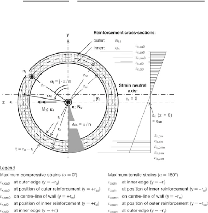
3.3.3 Annular reinforced concrete cross-sections
Figure 3.8 shows the strain condition in an annular reinforced concrete cross-section.
Converting the cylindrical coordinates into Cartesian coordinates:
y
wj
¼
r
w
cos
a
j
z
wj
¼
r
w
sin
a
j
with the indices w
¼
i (inner edge), si (inner reinforcement), m (centre-line of wall), sa
(outer reinforcement) and a (outer edge)
The individual pairs of values M
z
¼
M(
k
z
) are determined iteratively as follows:
a) Start values for iteration step k
¼
1:
Specify a curvature
k
z
for which the bending moment M
z
is to be found.
Specify the normal force action effect N
x
.
Calculate the start value of the concentric strain (i.e. compressive strain):
N
x
E
c0
A
c
þ
E
s
N
x
p þ
E
s
e
xk
¼
A
s
¼
E
c0
r
a
r
i
ð
a
si
r
si
þ
a
sa
r
sa
Þ
2
p
Fig. 3.8 Geometry of and strains in an annular reinforced concrete cross-section