Environmental Engineering Reference
In-Depth Information
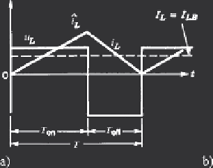
Fig. 4.17
Step-up converter, continuous and discontinuous conduction. (
a
) bondary case of
cont./discont. conduction; (
b
) boundary curves;
I
re f
=
U
o
T/L
increases again. The assigned average current
I
LB
is depending on the duty ratio
d
.
Figure 4.17b shows boundary curves of the output current
I
oB
and the inductor cur-
rent
I
LB
, when the output d.c. voltage
U
o
is kept constant. The following maximum
values apply:
I
LB
,
max
=
1
8
U
o
T
L
2
27
U
o
T
L
at
d
= 0
,
5;
I
oB
,
max
=
at
d
= 1
/
3
(4.14)
Note that the step-up converter is not suitable for no-load operation; the output
voltage must always be larger than the input voltage by at least 2 V. Control charac-
teristics are given in Fig. 4.18, again for output voltage
U
o
= const, indicating the
limit between continuous and discontinuous conduction.
Fig. 4.18
Step-up converter, control characteristics

Search WWH ::

Custom Search