Environmental Engineering Reference
In-Depth Information
a)
b)
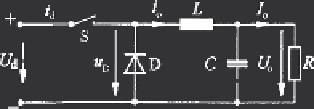
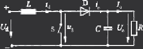
Fig. 4.16
D.c./d.c. chopper with inductor storage element. (
a
) Step-down (buck) converter; (
b
)
Step-up (boost) converter
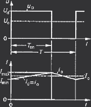
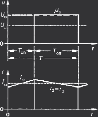
this applies to the (output) inductor current, dependent on conduction of switch and
diode. The performance of both converters is described under simplified conditions
(losses neglected) by Fig. 4.16. It is seen that the inductor is periodically loaded and
unloaded, the currents piecewise linear with time. To limit the current variation, a
minimum inductance value has to be applied which is inversely proportional to the
switching frequency
f
= 1
/
T
. Characteristic values are as follows:
Buck
Boost
Duty ratio
d
=
T
on
/
T
d
=
k
d
=(
k
−
1)
/
k
Voltage ratio
k
=
U
o
/
U
d
k
=
d
k
= 1
/
(1
−
d
)
k
−
1
I
=
U
d
L
I
=
U
d
L
Current variation
Δ
I
=
I
max
−
I
min
Δ
k
(
k
−
1)
Δ
k
U
d
T
Δ
U
d
T
Δ
k
−
1
Required inductance
L
≥
=
I
max
k
(
k
−
1)
L
≥
I
max
k
(4.13)
Figure 4.16 shows examples with continuous currents. Under different condi-
tion the current may be discontinuous. Here the step-up converter is considered to
discuss the limits between operation modes [Moh95]. In Fig. 4.17a is shown the
limiting case where the decreasing inductor current
i
L
is touching zero before it

Search WWH ::

Custom Search