Environmental Engineering Reference
In-Depth Information
The circuit may be considered as a special application of the active front-end
inverter, and performance analysis of voltage and current fundamentals derived from
4.3.3.3.
U
k
=
ω
L
k
I
N
U
N
R
k
I
N
U
N
→
∞
= 30%
= 2%
C
d
t
= 50 Hz
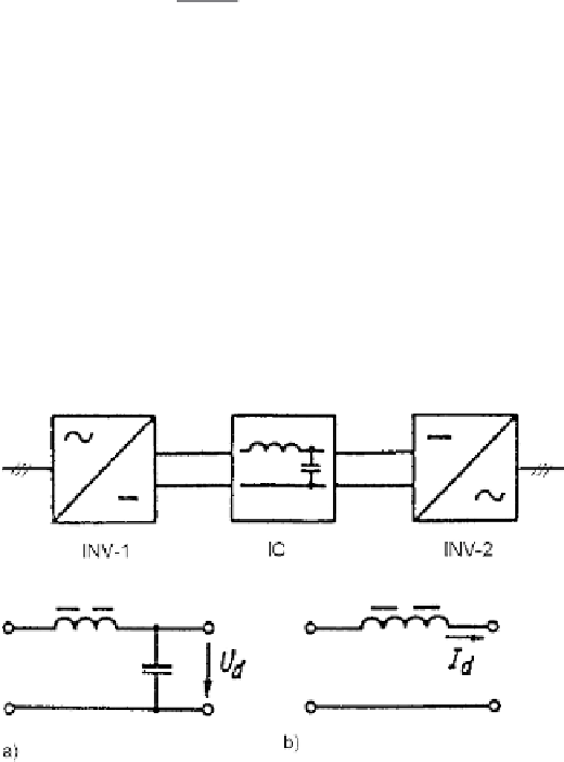
4.3.4 Converters with Intermediate Circuits
Power electronic devices converting a.c. power of one voltage and frequency to
another voltage and frequency are known as cyclic converters, matrix converters
and converters with intermediate circuit. Considering from the latter those with d.c.
intermediate circuit, we distinguish
- voltage-source inverters (VSI, U-converter) with a capacitor storage element;
- current-source inverter (CSI, I-converter) with an inductor storage element.
Figure 4.15 shows principle circuit representations.
Fig. 4.15
Converter schemes with intermediate circuits.
(
a
) voltage-source inverter (VSI); (
b
)
current-source inverter (CSI)
4.3.5 D.c./d.c. Choppers
Typical d.c/d.c. converters are shown in Fig. 4.16 [Moh95]. The input voltage
U
d
is transformed to the adjustable output value
U
o
, with either a step-down (buck) or
step-up (boost) ratio. A suitable semiconductor element such as a transistor, repre-
sented in the circuits as a switch S, is periodically switched on and off, controlled
by pulse-width modulation (PWM). An inductance
L
serves as storage element. In
normal service, with continuous inductor current, the performance is such that in
the buck converter the input current is discontinuous, while in the boost converter
Search WWH ::

Custom Search