Environmental Engineering Reference
In-Depth Information
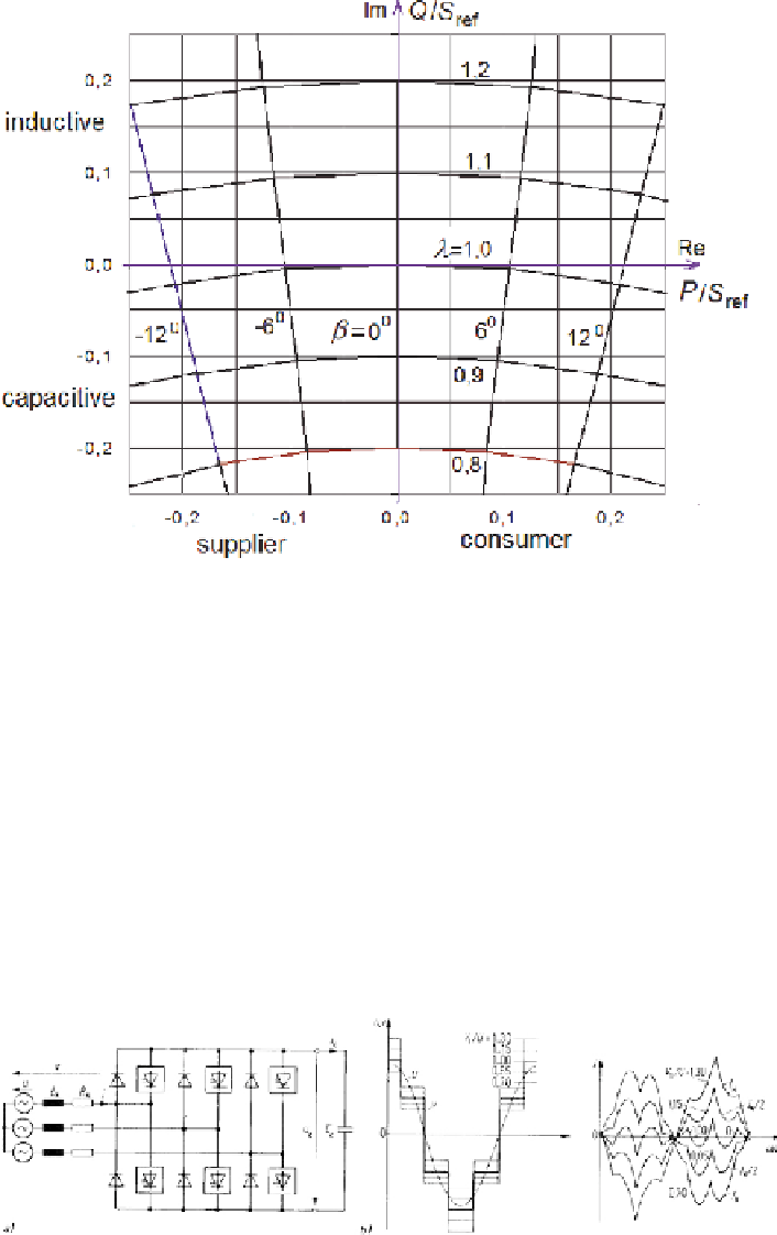
Fig. 4.13
Power locus diagram in consumer (motor) coordinates, for lossless inductor
machine requiring magnetizing reactive power and acting as generator operates in
the second quadrant of the figure.
4.3.3.4 Reactive Power Voltage-Source Inverter
Figure 4.14 describes a reactive power inverter with capacitor storage element,
shown for square-wave operation [Heu96]. Unlike the current-source inverter des-
cribed in 4.3.2.2 this self-commutated voltage-source converter is capable of pro-
ducing capacitive (overexcited) as well as inductive (underexcited) reactive power.
The circuit may readily be adapted for PWM operation.
Fig. 4.14
Reactive power inverter with capacitive storage element, in square-wave operation (
a
)
circuit; (
b
) voltage and currents (example)
Search WWH ::

Custom Search