Environmental Engineering Reference
In-Depth Information
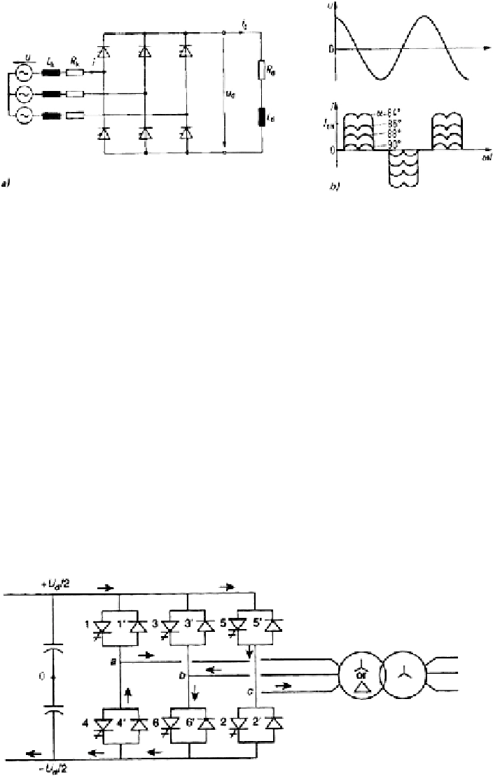
Fig. 4.6
Reactive power inverter with inductive storage element (
a
)circuit;(
b
) voltage and currents
(example)
4.3.3 Self-Commutated Inverters
4.3.3.1 Three-Phase Full Wave Bridge Inverter
In self-commutated inverters the commutation voltage must be generated within the
power electronic device. Generally this requires semiconductor elements with gate
turn-on and turn-off capability, such as MOSFETs, bipolar transistors, IGBTs or
GTOs. Figure 4.7 shows a voltage source inverter in three-phase B6 arrangement,
characterized by diodes anti-parallel to the switching elements in the branches.
When controlled in full-wave, six-step operation (or as block inverter), the volt-
ages appear as shown in Fig. 4.8, where d.c. voltage
U
d
is assumed constant. Figure
part a) are the voltages at the a.c. output with respect to point 0. Part b) shows the
line-to-line voltages, part c) is one of the phase voltages with respect to neutral point
N of the transformer winding in Y connection. Eventually figure part d) depicts the
voltage between d.c. reference 0 and a.c. neutral N.
Fig. 4.7
Full-wave bridge voltage-source inverter
Search WWH ::

Custom Search