Environmental Engineering Reference
In-Depth Information
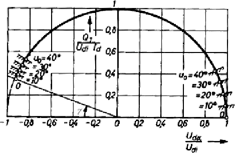
Fig. 4.5
Circle diagram showing the relation between d.c voltage and control-reactive power (
u
0
values indicate initial commutation overlap angles)
In the field of wind energy conversion systems the inverter with B6 thyristor
bridge is applicable to the classical super-synchronous cascade, identical to the static
Kramer system. It must be noted that in variation of the firing angle
not only
adjusts the average d.c. voltage, but also a reactive power is drawn from the grid
which assumes its maximum (equal to the active power at
α
/
2.
The reactive power
Q
is inductive (underexcited). Its fundamental value due to phase
control is:
α
= 0) when
α
=
π
Q
1
,
c
=
U
di
I
d
sin
α
(4.5)
When taking the reactive power due to commutation also into account, we get:
Q
1
=
U
di
I
d
1
R
x
I
d
/
U
di
)
2
−
(cos
α
−
(4.6)
Figure 4.5 shows the relevant circle diagram [Heu96].
4.3.2.2 Reactive Power Current-Source Inverter
While reactive power consumption in circuits with thyristor controlled B6 circuits is
mostly considered a drawback because of the poor power factor on the a.c. side when
adjusting the d.c. voltage to lower values, a variant of the current source inverter may
find application as an adjustable reactive power generator. In the circuit of Fig. 4.6
the d.c. side contains an inductor as storage element. Firing angles of nearly 90
◦
allow to adjust reactive power. Since the commutation voltage must be delivered by
the grid side, the device can only generate inductive reactive power.
The circuit is a controllable static var compensator (SVC), of which use is made
in FACTS technology for shunt-connected controllers. With regard to wind energy
systems the device can serve to control the voltage of a self excited induction gen-
erator (SEIG), together with a capacitor bank.
Search WWH ::

Custom Search