Environmental Engineering Reference
In-Depth Information
In Figure 3.6a applying to a machine with short-circuited rotor winding, where
current-displacement in conductors is neglected, the current locus is a circle . The
figure may also serve for a graphical method to determine power and torque values.
Consider a machine operating at complex primary current
I
corresponding to point
P
on the circle. Of the indicated straight lines, 1 is a diameter defined by the no-load
point
P
0
and the circle centre
m
. 2 is the line for zero air-gap power and torque,
respectively. 3 is the line of zero mechanical power, when friction and windage
losses are neglected. The torque is then proportional to the length of a line (
P
, line 2),
drawn perpendicular to the diameter 1. Similarly, the mechanical power is found
proportional to the length of a line (
P
, line 3), drawn perpendicular to the diameter 1.
It is understood that scale factors of power and torque have to be derived from the
scale factor for current, using the constant values of
U
1
and
ω
1
, respectively, and
taking the per-phase nature of the equivalent circuit model into account.
Figure 3.6b is a vector diagram, indicating approximately rated generator opera-
tion. It reflects the circuit equations according to Kirchhoff's law. Note that the slip
is negative, with a magnitude of a few percent or below. The main field voltage
U
m
,
appearing at the reactance
X
m
in the equivalent circuit, is leading the magnetizing
current
I
μ
by a right angle. In view of the physical properties, the rotor-side resistive
parameter may be separated into two components,
R
2
s
1
−
s
=
R
2
+
R
2
,
s
i.e. by the actual resistance and a slip-dependent component called the useful
resistance which may be positive for 1
>
s
>
0, negative for
1
<
s
<
0. The dia-
gram takes care of this distinction, showing the ohmic voltage drop and the torque-
building voltage component which is in the generator case in opposite phase with
the current.
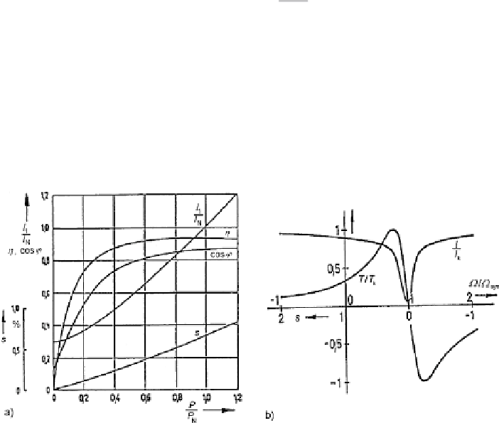
Figure 3.7a shows the performance characteristics of a typical induction motor
for industry drives application (90 kW, frame size 280, four poles) when supplied by
−
Fig. 3.7
Operation at rated voltage (
a
) Performance characteristics; (
b
) Current and torque vs.
speed and slip
Search WWH ::

Custom Search