Environmental Engineering Reference
In-Depth Information
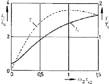
Fig. 3.5
Principal
characteristics of current and
torque at constant flux linkage
abscissa is scaled in normalized rotor frequency (
ω
2
τ
k2
). It can be observed that at
ω
2
= 1
/
τ
k2
the developed torque is the break-down value
T
k
.
3.2.2.3 Grid Operation
When a stator voltage of constant frequency is given, as in grid operation, alternative
expressions to calculate the complex currents and torque are preferred. Different
from (3.2) and (3.3) reference parameters are now the values of stator-side short-
circuit reactance
X
k
and break-down slip
s
k
, again neglecting stator resistance.
I
2
I
1
+
js
/
s
k
1 +
js
/
s
k
js
/
s
k
U
1
jX
k
σ
X
m
X
2
I
1
=
;
=
−
(3.5)
σ
+
js
/
s
k
s
k
=
R
2
/
(
X
2
)
where
X
k
=
σ
X
1
;
σ
U
1
2
ω
1
2
s
/
s
k
1 +(
s
/
s
k
)
2
T
k
=
z
p
3
2
1
−
σ
X
k
T
=
T
k
where
The current formula amended for taking stator resistance into account is given by:
U
1
jX
k
σ
+
js
/
s
k
I
1
=
where
ρ
1
=
R
1
/
(
σ
X
1
)
(3.6)
(1 +
ρ
1
·
s
/
s
k
)+
j
(
s
/
s
k
−
σ ρ
1
)
Here
ρ
1
is a primary damping coefficient
3.2.2.4 Complex Locus and Vector Representation
In the equations of current (3.5, 3.6) the slip
s
can be considered as independent
parameter. With the definition:
s
=
ω
2
z
p
·
Ω
ω
1
ω
1
= 1
−
(3.7)


Search WWH ::

Custom Search