Environmental Engineering Reference
In-Depth Information
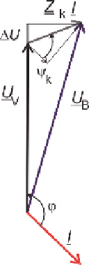
Fig. 7.1
Model of
short-circuit impedance
between generator and grid
and voltage variation
a)
b)
The WES is modeled by the generator symbol which includes line and trans-
former impedance components between terminals and connection point, referred to
the relevant nominal voltage. In an example of a WES connected to medium volt-
age 20 kV, with a transformer 110/20 kV feeding into the distribution system, where
S
k
= 120 MVA referred to the 20 kV-side, the short-circuit impedance is given by:
ψ
k
= 51
◦
Z
k
=(2
,
1 + j2
,
6)
Ω
;
|
Z
k
|
= 3
,
342
Ω
;
Current regulations require WES to declare a factor
k
ψ
, of influence for switching
actions, which depends on the phase angle
ψ
k
of the short-circuit impedance
Z
k
.
Consider a generator operating at an apparent power
S
=
P
+ j
Q
, the voltage
variation at CP is approximately:
U
aV
=
R
k
I
P
S
+
X
k
I
Q
I
S
(
R
Δ
=
·
P
+
X
·
Q
)
S
When the generator is operating at rated values, with current
I
N
and power factor
cos
ϕ
N
, the relative voltage increase becomes:
u
aV
=
Δ
U
aV
U
N
=
Z
k
I
N
U
N
Δ
cos(
ψ
kV
−
ϕ
N
)
Note that the angles are in consumer system notation, where the sign of a lag-
ging current (with respect to voltage) is positive, and the sign of the ohmic-inductive
impedance
Z
k
is positive. In Fig. 7.1b an example vector diagram is shown which re-
flects the above equation under the condition that
1. Note that in this
case
U
B
>
U
V
due to the case of a directly coupled asynchronous generator draw-
ing its magnetizing current component from the grid. Theoretically, in the above
example the voltage deviation would become zero when operating the generator at
ϕ
|
U
B
/
U
V
−
1
|
= 141
◦
.


Search WWH ::

Custom Search