Environmental Engineering Reference
In-Depth Information
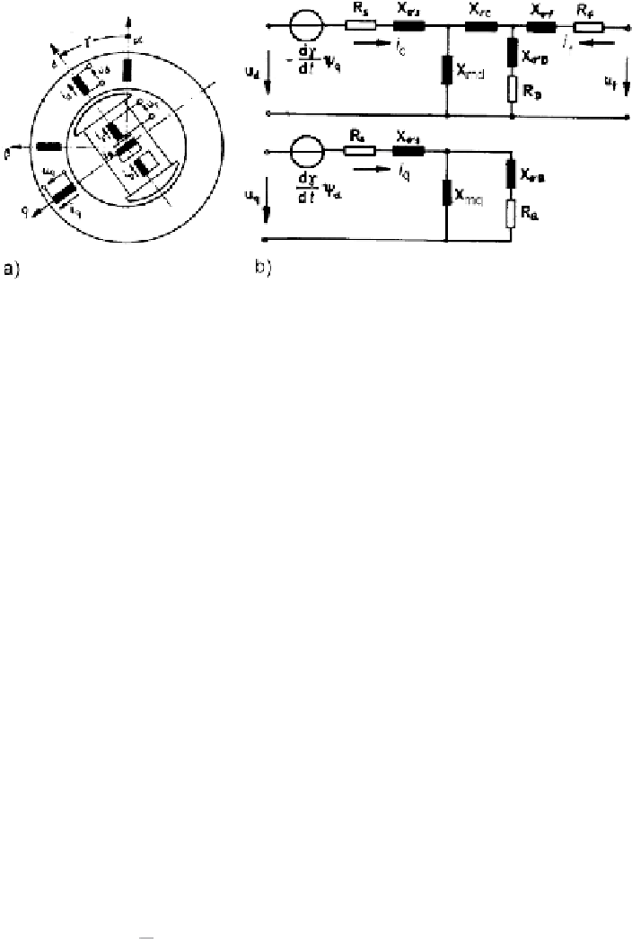
Fig. 6.6
Model of the synchronous machine with five windings (
a
) windings arrangement in d,q
components; (
b
) equivalent circuit model
coupling reactance value
X
rc
may be positive (as in turbogenerators) or negative (as
in many salient-pole machines). Frequently, the machine model is simplified using
X
rc
= 0, resulting in larger errors of calculated rotor quantities.
6.2.3.5 Reactance Operators and Frequency Response
The model of (6.31) and Fig. 6.6 may alternatively be described in terms of transient
and subtransient reactances (or inductances) and time-constants. Most of them can
be determined by tests.
A well-known model representation is by means of reactance operators, which
are complex functions of the differential operator
p
[IEC60034, part 4]. Using this
approach, the voltage equation is:
u
d
(
p
) =
R
s
i
d
(
p
) +
p
ψ
d
(
p
)
−
ωψ
q
(
p
)
(6.44)
u
q
(
p
)=
R
s
i
q
(
p
)+
p
ψ
q
(
p
)+
ωψ
d
(
p
)
where
dt
The flux linkages are in operator representation:
=
d
ω
q
(
p
)=
X
q
(
p
)
i
q
(
p
)
ωψ
d
(
p
)=
X
d
(
p
)
i
d
(
p
)+
G
f
(
p
)
u
f
(
p
) ;
ωψ
(6.45)
With known flux operators the currents may be calculated:
G
f
(
p
)
X
d
(
p
)
u
f
(
p
)
i
d
(
p
)=+
ωψ
d
(
p
)
i
q
(
p
)=
ωψ
q
(
p
)
X
q
(
p
)
X
d
(
p
)
−
;
(6.46)
Search WWH ::

Custom Search