Environmental Engineering Reference
In-Depth Information
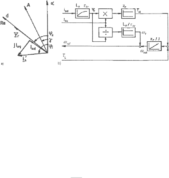
Fig. 6.4
Rotor model of induction machine (
a
) Space-vector diagram; (
b
) block diagram
Choosing the rotor flux space vector as reference, it is positioned in the d-axis
which is also the real axis. Hence (6.20) expressed by components becomes:
τ
0
r
d
ψ
r
dt
L
s
i
sd
=
ψ
r
+
where
ψ
r
=
ψ
rd
=
ψ
r
(6.21)
L
s
i
sq
=
τ
0
r
ω
r
ψ
r
where
ω
r
=
ω
re f
−
ω
rot
The electromagnetic torque is expressed by:
T
el
=
3
2
z
p
i
sq
ψ
r
(6.22)
It is seen that the torque is defined by the product of q-axis current and d-axis
flux; consequently
i
q
is called the torque building component and
i
d
the flux-building
component. The equation of motion for the one-mass inertia model is:
J
d
ω
rot
dt
=
T
el
+
T
L
(6.23)
Figure 6.4 shows space vector diagram and a block diagram representation of
the rotor model based on (6.20-6.22). In the figure the rotational speed is calculated
according to (6.23) which of course may be replaced when a measured speed value
is available.
In Fig. 6.4b
i
sd
,
i
sq
and
T
L
are the input values; calculated results are
r
and
T
el
. To apply the rotor model, the current components may be obtained from mea-
sured currents in stator frame by a transformation, when the rotor angular frequency
is known from measurement or estimation. For flux oriented control, rotor flux and
torque signals serve as the actual values.
ψ
r
,
ω
6.2.2.4 Transient Model
In order to calculate the behavior of a cage induction machine subjected to varia-
tions of the load torque a transient model can be used. Consider a machine operating
Search WWH ::

Custom Search