Environmental Engineering Reference
In-Depth Information
a)
b)
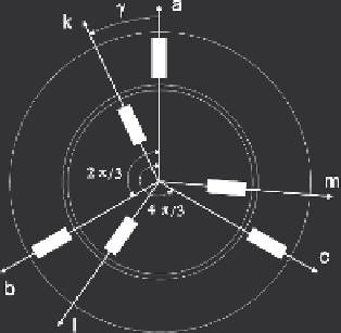
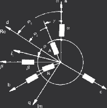
Fig. 6.1
Three-phase machine model and coordinates (
a
) three-phase windings in stator and rotor;
(
b
) different frames
same (direction a =
). Regarding the rotor, transformed components are A, B, ass-
igned to original components k, l, m. The zero-sequence component is not shown
in the figure; it may be drawn separately because according to the machine model it
does not contribute to torque production.
Park's transformation (6.5) assigns components d, q to the original components.
Reference axis d may be chosen arbitrarily. Using a common coordinate system for
stator and rotor quantities,
α
ϕ
in the transformation according to (6.5) will be
ϕ
=
ϕ
1
for stator and
ϕ
2
for rotor quantities, see Fig. 6.1. In synchronous machines
the coordinate system is generally fixed to the rotor, with the pole-axis as reference.
When the d, q components are expressed by a complex quantity,
g
s
=
g
α
+ j
g
β
,the
d-axis is the real axis.
It may be mentioned that the use of modal components are not restricted to three-
phase a.c. machines, but finds wide application in the analysis of power distribution
networks.
ϕ
=
6.2.2 Asynchronous Machine Models
6.2.2.1 Model in
αβ
-Coordinates
The machine to be considered carries a symmetrical three-phase winding in the
stator. The rotor may be a wound rotor with slip-rings, or a cage rotor. For purpose
of the model, the rotor impedance is considered independent of slip (i.e. no current
displacement taken into account), the air-gap is constant and magnetic saturation
effects are neglected. Skin-effect in rotor conductors and iron saturation may be
taken into account in a refined model later.
Describing the electrical system of asynchronous machines, the windings are rep-
resented in stator and rotor by two orthogonal windings on each member. Figure 6.2
Search WWH ::

Custom Search