Environmental Engineering Reference
In-Depth Information
a)
b)
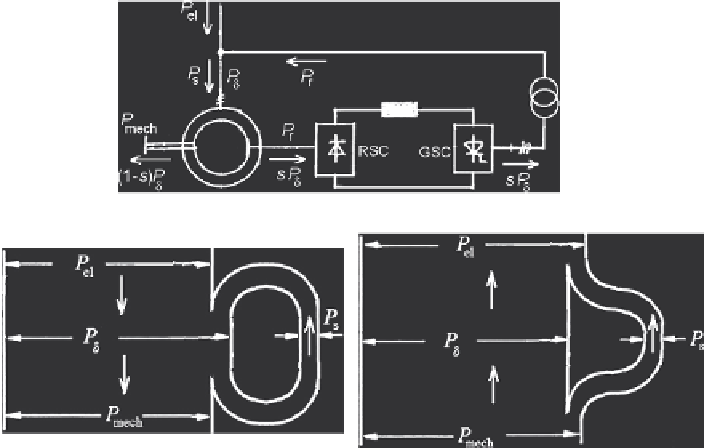
Fig. 5.11
Visualization of Kramer cascade operation (
a
) Diagram for slip power recovery
(losses neglected); (
b
) Sankey diagrams; left: motor operation (
s
>
0); right: generator operation
(
s
<
0)
P
M
=
P
δ
;
Q
M
=
P
δ
·
tan
ϕ
M
P
W
=
−
s
·
P
δ
=
−
P
s
;
Q
W
=
−
s
·
P
δ
·
tan
α
W
P
el
=
P
M
+
P
W
=(1
−
s
)
·
P
δ
=
P
mech
;
Q
G
=
Q
M
+
Q
W
=
P
δ
·
(tan
ϕ
M
+ tan
α
W
)
(5.7)
Note that the air-gap power
P
δ
transferred from stator to rotor is negative when
the slip is negative (supersynchronous). Due to the uncontroled rectifier, active
power can only flow from the rotor to the converter; hence the slip power must
be positive,
P
s
=
s
P
δ
>
0.
The main drawback of this concept is a high reactive power demand, consisting
of the machine magnetizing component and the inverter control component. Hence
a low overall power factor is obtained which becomes poorer as the speed control
ratio is increased. Hence ratios of
n
max
/
n
min
>
1
,
5 are considered impropriate for
practice.
Figure 5.12a shows the principal graph of torque vs. speed (or slip, respectively).
The limit of variable speed operation was set to
·
= 0
,
5 by appropriate design
of the phase-controlled grid-side converter. Any permissible operation in the quad-
rants I (motor, subsynchronous) and III (generator, supersynchronous) of Fig. 5.12a
can be realized, whereas quadrants II and IV are not possible for the circuit given
in Fig. 5.9. Figure 5.12b illustrates the power characteristics of the Kramer system
with
k
2
= 0
,
1, both in motor und generators mode.
|
s
0
,
max
|
Search WWH ::

Custom Search