Environmental Engineering Reference
In-Depth Information
a)
b)
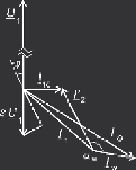
Fig. 5.10
Steady state operation of the wound rotor induction machine (
a
) complex current locus
for constant rotor voltage (s
0
=
±
0
,
1 as example); (
b
) phasor diagram for operation as a generator
in Fig. 5.10a illustrates an example for
k
2
= 0
,
1 = const of a machine having a
breakdown slip
s
k
= 0
,
303. Note that the circle has two slip scales, the exterior for
s
0
=
0
,
1, and the interior for
s
0
=
k
2
= 0
,
1. Quantities
s
0
are no-load slip
values in cascade operation.
It becomes evident that subsynchronous motor operation and supersynchronous
generator application is obtained with the same circuit. In the case of an uncon-
trolled rotor side rectifier the hatched parts in Fig. 5.10a would require active power
supplied to the rotor which cannot be realized when the diode rectifier is used.
A principal phasor diagram is shown in Fig. 5.10b for negative slip, s =
−
k
2
=
−
−
0
,
35.
·
As mentioned, phasors
U
1
and (s
U
1
) are in phase opposition. Note that the
/
2, is exaggerated in length in the figure.
Rotor current
I
2
is transformed to the grid side current
I
W
by action of the in-
verter, producing a phase angle
magnetizing current
I
10
, lagging by
π
α
W
∼
5
/
6
·
π
. The resulting generator current
is
I
G
.
Both supersynchronous and subsynchronous operation can be illustrated by a
power diagram. Figure 5.11 illustrates the flow of power components in the Kramer
cascade, neglecting the losses. Figure 5.11a is a simplified block diagram, where the
arrows indicate positive direction. The slip power is recovered from the rotor side,
adapted to the grid side in the converter, and merges with the stator power resulting
in the cascade electrical power. Figure 5.11b shows simplified Sankey diagrams,
relevant for motor operation (
s
>
0) and generator operation (
s
<
0).
The simplified power balance is established under the same assumption of ne-
glecting the losses. The following equations describe active power quantities
P
and
reactive power quantities
Q
, as for the machine stator side M, the converter W, and
the resulting grid values.


Search WWH ::

Custom Search