Environmental Engineering Reference
In-Depth Information
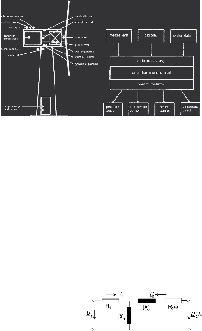
Fig. 5.7
Operation and control of a wind energy system. Sketch of data acquisition (
left
) and block
diagram of operation management (
right
)
where
U
1
,
U
2
are the stator voltage and the rotor voltage vector referred to stator
side, respectively. Note that in steady state the rotor quantities are of slip frequency
(
s
f
1
).
When neglecting the stator resistance
R
1
in Fig. 5.8, which is permissible for
most performance calculations not intending to render correctly the machine losses,
currents and powers can be determined by a set of complex equations.
Rotor and stator current are calculated:
·
e
j
ϕ
2
1
X
σ
U
2
−
U
1
s
s
k
+
js
=
U
1
X
σ
k
2
·
−
s
I
2
=
; where
s
k
is the breakdown slip
s
k
=
R
2
/
X
σ
s
k
+
js
U
1
jX
1
I
2
I
1
=
I
0
−
mit
I
0
=
(5.4)
Stator and rotor apparent powers are:
I
1
=
P
1
+
jQ
1
I
2
=
P
2
+
jQ
2
S
1
= 3
U
1
·
;
S
2
= 3
U
2
·
(5.5)
where
I
∗
denotes the conjugate complex of
I
. Note that a machine with three-phase
windings both in stator and rotor is assumed, and
U
,
I
are per-phase values.
Fig. 5.8
L-model for
asynchronous wound-rotor
machines


Search WWH ::

Custom Search