Environmental Engineering Reference
In-Depth Information
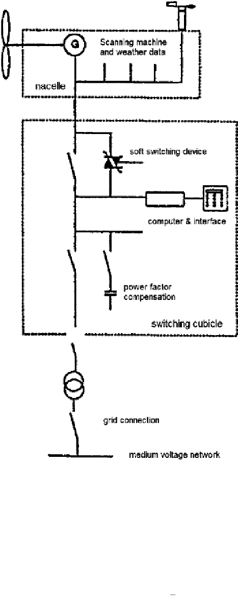
Fig. 5.6
Principle diagram of a constant speed system
Note that in comparison with (3.2) rotor voltage and current referred to stator
side are now
I
2
=
I
2
/
k
Γ
and
U
2
=
U
2
·
k
.
When investigating different cascade circuits it is useful to define the rotor side
voltage in relation to the stator voltage
U
1
, using a complex ratio
γ
, expressed by
the real factor
k
2
and the phase displacement
ϕ
2
:
U
2
=
U
1
·
γ
e
j
ϕ
2
=
k
2
·
U
1
·
(5.3)
Search WWH ::

Custom Search