Environmental Engineering Reference
In-Depth Information
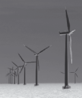
(a)
(b)
FIGURE 2-3
Common offshore wind turbines: (
a
)
Vestas 3-MW turbines with
90-m rotor diameters and 70-m hub heights at Thanet in the United Kingdom.
The turbines are on monopile foundations.
(
b
)
Siemens 2.3-MW turbines with
83-m rotor diameters and 69-m hub heights at Nysted off of Denmark. These
turbines are on gravity-base foundations. (S
OURCE
: Vestas, Siemens.)
of a conventional reinforced concrete mat poured below grade with the
use of conventional construction methods. In contrast, an offshore wind
turbine requires a substructure of tens of meters in height to elevate the
base of the turbine tower above sea level. The most common offshore sub-
structure type, accounting for approximately 80 percent of all offshore
turbine installations, is the monopile—a large steel cylinder with a wall
thickness of up to 60 mm (2.36 in.) and a diameter of up to 6 m (19.7 ft).
Figure 2-4 shows four commonly used substructures. A less frequently
used substructure, suction caissons, is shown in Figure 2-5.
In sands and soft soils, steel monopiles have been driven in water depths
ranging from 5 to 30 m (16.4 to 98.4 ft). In stiff clays and other firm soils,
they can be installed by boring or using a combined driven-drilled option
with a pile top drill (Fugro-Seacore 2011). The embedment depth varies
with soil type, but typical North Sea installations require pile embedment
25 to 30 m (82 to 98.4 ft) below the mud line. A steel transition piece is fit-
ted around the section of the monopile that protrudes above the waterline,
and the gap between the two steel pieces is grouted, which provides a level
flange on which to bolt the tower base. The monopile foundation requires


Search WWH ::

Custom Search