Environmental Engineering Reference
In-Depth Information
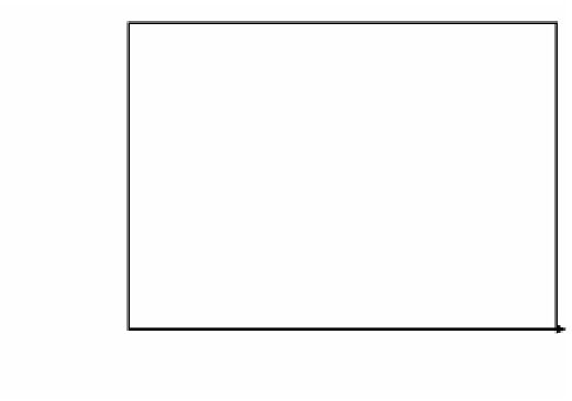
Modeled Pattern
r
2
Real Pattern
r
1
0.0
τ
1.0
Normalized material residence time in furnace
1
1
(
)
()
=
∫
(
)
∫
()
fr
fr t dt CT
=
3
1
+
r
+
r
2
+
r dt
3
(2.9)
T
T
r
out
T
T
T
0
0
The range of the integration of the
Figure 2.25
is given when integral variable
t
is converted to
r
T
. The temperature of the combustion gas at the furnace entrance,
T
gin
, is assumed to be the maximum temperature of the gas,
T
fmax
, and the temperature
at the furnace exit
T
gout
as
T
out
.
T
T
T
T
T
T
T
T
m
m
m
m
r
==
,
r
= =
in
in
out
out
1
2
g
f
g
f
in
max
out
max
The temperature of the heated material at the furnace exit can be given by using
the heat quantity of the heated materials.
Tm
Q
Cm
T
=
+
(
m
(2.10)
)
m
in
˙
out
m
The amount of convection heat transfer gained by the heated materials is given
by Equation 2.10 obtained by treating the convective heating process as a parallel
flow type of heat exchanger.
(
)
=
(
)
(
)
˙
Q
1-
ξ
Cm
T
−
T
conv
m
m
mix
m
in
{
}
(
{
}
=
(
)
+
(
)
)
+
(
)
T
CmT
˙
CmT
˙
Cm
˙
Cm
˙
(2.11)
mix
in
f
in
m
in
m
max
in
(
)
ξ
=
exp -
bKL
m
m
m
m


Search WWH ::

Custom Search