Environmental Engineering Reference
In-Depth Information
Fuel flow meets
with preheated air
here
140mm
Air
Fuel
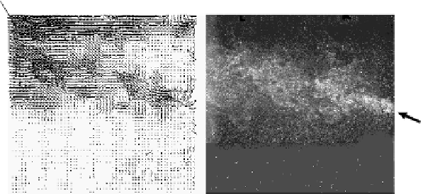
PIV result
Direct photograph
FIGURE 2.23
Results of measuring the in-furnace flow by PIV, condition (d), in-furnace
temperature 950˚C (F2 mode).
In either figure, the side image shows a laying of a velocity vector besides the
measured photograph.
Figure 2.23
shows a color bar at a maximum velocity 34 m/s.
The velocity in terms of magnitude is the same in both
Figures 2.22
a
nd
2.23
,
but
the position where the fuel jetting diffusion comes across the airflow to start com-
bustion is much different. It has been found from the loci of velocity vectors that
the combustion starting position is 140 mm downstream (divergent angle: 22˚) under
condition (c) and 92 mm downstream (divergent angle: 25˚) under condition (d).
2.2.3.4 Summary
The optical measurement was carried out to investigate the characteristics of the
flame having a similar structure to high temperature air combustion in an actual
furnace using regenerative burners. In the case of a flame generated by the usual
combustion condition, the combustion reaction takes effect suddenly with fresh
airflow. Without dilution of airflow caused by entrained flue gas, a very high tem-
perature results. This causes a high concentration NO
x
emission as well. However,
in the case of the distributed flame of F2 mode, the fuel is taken into the airflow to
start combustion at an earlier stage when the fuel jetting is oblique to the airflow,
compared with the case of fuel parallel jetting. This results in a high concentration
NO
x
emission as well. From these results, it has been confirmed that the concentra-
tion of NO
x
emitted is lowered under these conditions such that a diffused mixing
at the initial stage is controlled. Also the fuel is mixed with the airflow in the state
of a low oxygen concentration in the wake where the self-EGR is enhanced.


Search WWH ::

Custom Search