Environmental Engineering Reference
In-Depth Information
2.2.2.4 Flow Patterns
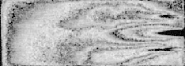
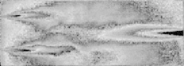
Flow patterns of the two modes of the fuel-air nozzle configurations, i.e., Mode II
and Mode III, were investigated to see what occurs in the mixing process in the
furnace. Results shown in
Figure 2.11
clearly show that each mode creates a very
different flow pattern in the model furnace. Flow pattern distribution obtained for
Mode II
(
Figure 2.11a
)
shows that fuel flow and airflow are issued into the furnace
in a parallel fashion and that the mixing is moderate. In Mode II, proper preparation
of the fuel-air dilution process occurs to cause the high temperature combustion
phenomena. Mode III (
Figure 2.11b
)
also demonstrates that sufficient fuel-air prep-
aration occurs for the high temperature combustion and that the general features of
the flow dynamics are very similar to those obtained for Mode II.
The observed flow patterns in Mode II and Mode III, therefore, suggest that
high temperature air combustion conditions are strongly related to the mixing process
and flow patterns in the entire furnace space. In contrast, ordinary combustion is
highly sensitive to mixing for flame holding in the nozzle near field. The flames
corresponding to Mode II and Mode III observed in the furnace had enlarged flame
volume and the furnace space seemed to be mostly filled with low luminosity flames.
We can treat the flames in Modes II and III as well-stirred reactors. Note that high
temperature air combustion was not caused by the agitating momentum although it
has similar features to that of the well-stirred reactors.
(a) Mode II parallel flow type
(b) Mode III counter flow type
1.0
0.5
0.0
FIGURE 2.11
Measured flow patterns.


Search WWH ::

Custom Search